
Build Your Part
- Price Not Available
- Price Not Available
-
-
0.000.00
Summary
Change configuration| {{summaryItem.Description}}: | None |
|---|---|
Classified Shapes
Clearance
DAYTON will assure the proper clearance of matrixes to the punch when ordered in this manner.
 Standard Ball Seat Locations
The Standard Ball Seat Location is at 90°. Alternate locations of 0°, 180° or 270° can be specified at no additional cost.
Custom Ball Seat Locations
Custom Ball Seat Locations can be specified as BS and degrees counter-clockwise from 0°.
Views
Views are: reflected view of punch and plan view of matrix.
Corner Dimensions (1) (2)
Dimensions should be to the theoretical sharp corners for C22, C24, C25, C34, C61 and C88. Some reduction of these dimensions will result from fitting the punch and matrix under conditions where clearance is .0015 or less per side.
Fillets matched with sharp corners reduce the clearance per side (i). If the clearance is .0015i or less, DAYTON will break sharp corners when the punches and matrixes are ordered together. This reduces assembly time and the risk of the edge breaking during operation.
Check your P&W dimensions to be certain the diagonal G does not exceed the maximum shown.

C10 (H)

C11 (K)

C12 (N)

C13

C14

C15

C16

C17

C18

C19

C20

C21

C22

C23

C24

C25

C26

C27

C28 (J)

C29

C30

C31

C32

C33 (V)

C34

C35

C36

C37

C38

C39

C40

C41

C42

C43

C44

C45

C46

C47

C48

C49

C50

C51

C52 (Y)

C53

C54

C55

C56

C57

C58

C59

C60

C61

C62

C64

C65

C66

C67

C68

C69

C70

C71

C72

C73

C74

C75

C76

C77

C78

C79

C80

C81

C82

C83

C84

C85 (Z)

C86

C87

C88

C89

C90

C91

C92

C93

O

R

| Component Brand | Press-Fit |
|---|---|
| Measure | Metric |
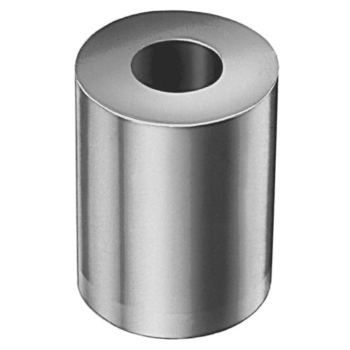
| Component Type | Headless Die Button |
| Punch Shape | Classified Shapes |
Classified Shapes
Clearance
DAYTON will assure the proper clearance of matrixes to the punch when ordered in this manner.
Standard Ball Seat Locations
The Standard Ball Seat Location is at 90°. Alternate locations of 0°, 180° or 270° can be specified at no additional cost.
Custom Ball Seat Locations
Custom Ball Seat Locations can be specified as BS and degrees counter-clockwise from 0°.
Views
Views are: reflected view of punch and plan view of matrix.
Corner Dimensions (1) (2)
Dimensions should be to the theoretical sharp corners for C22, C24, C25, C34, C61 and C88. Some reduction of these dimensions will result from fitting the punch and matrix under conditions where clearance is .0015 or less per side.
Fillets matched with sharp corners reduce the clearance per side (i). If the clearance is .0015i or less, DAYTON will break sharp corners when the punches and matrixes are ordered together. This reduces assembly time and the risk of the edge breaking during operation.
Check your P&W dimensions to be certain the diagonal G does not exceed the maximum shown.
C10 (H)
C11 (K)
C12 (N)
C13
C14
C15
C16
C17
C18
C19
C20
C21
C22
C23
C24
C25
C26
C27
C28 (J)
C29
C30
C31
C32
C33 (V)
C34
C35
C36
C37
C38
C39
C40
C41
C42
C43
C44
C45
C46
C47
C48
C49
C50
C51
C52 (Y)
C53
C54
C55
C56
C57
C58
C59
C60
C61
C62
C64
C65
C66
C67
C68
C69
C70
C71
C72
C73
C74
C75
C76
C77
C78
C79
C80
C81
C82
C83
C84
C85 (Z)
C86
C87
C88
C89
C90
C91
C92
C93
O
R
- Component Brand:
- Press-Fit
- Measure:
- Metric
- Component Type:
- Headless Die Button
- Punch Shape:
- Classified Shapes
You might also be interested in the following products
Configure Product
- {{segmentOption.Description}}
-
{{segmentOption.Description}}
- {{segmentOption.Description}}
| {{summaryItem.Description}}: | None |
|---|---|
We’re the industry-leader in the production of manufacturing tools such as special punches, die components, die details, punch blanks and metal-stamping tools.
Get In Touch