Birth of a Hole - Perforating Basics
The Perforating Process
Program Objectives
- Define Die Clearance
- Illustrate the Six Steps of the Perforating Process
- Explain the Advantages of using Engineered Die Clearance
- Simplify Maintenance of Ejector Type Punches
The dynamics of the perforating process are often considered to be a simple two-step process of driving a punch through a piece of sheet steel and then withdrawal of the punch from the hole.
There are in fact six steps to perforating a hole. This portion of the program will illustrate each of those steps in detail.
Clearance
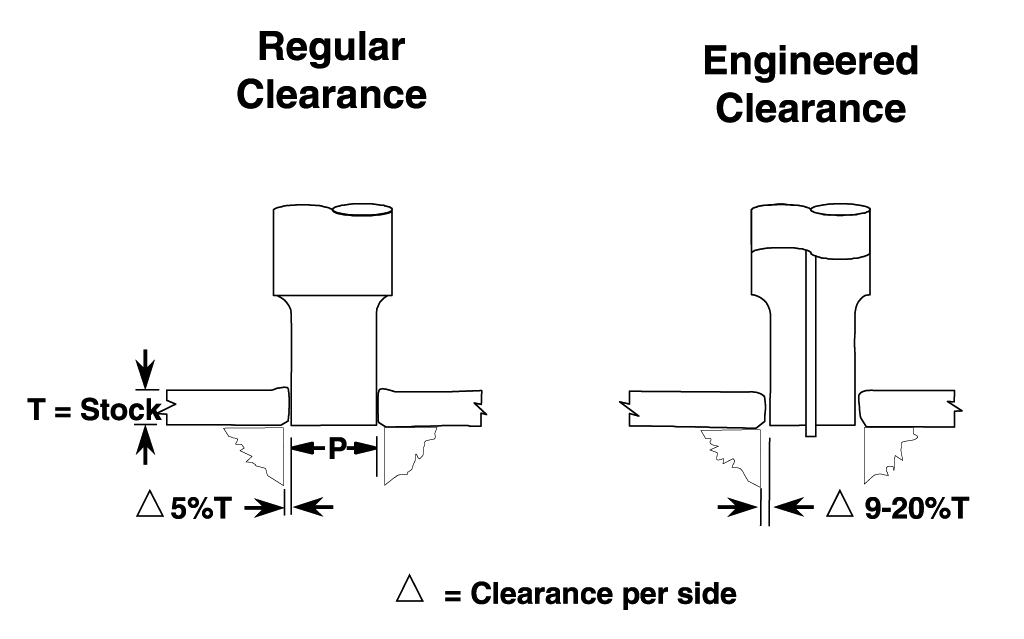
For many years toolmakers used 5% of stock thickness per side as a standard punch to die clearance. This provided an acceptable burr height and slug control. Research and testing has revealed that a radical increase in punch to die clearance can reduce burr height to the lowest point while increasing tool life by several times.
The side effect to this approach is slug pulling. A spring loaded ejector pin extending from the center of the punch face will solve the slug pulling in most cases.
There are two ways in which punch to die (matrix) clearance can be described. They are Total and Per Side. To minimize confusion, this program will use Clearance Per Side as the standard. The Delta symbol (i) is used to indicate Clearance Per Side.
Clearance Per Side is the distance between the cutting edges of the punch and matrix. This distance between punch and matrix is maintained around the entire perimeter.
Example: Engineered Clearance of 10% Per Side for .060" thick material: (.060" x .10 = .006")
| 10% Per Side Clearance x 2 | .012" |
| Punch Point Size | + .500" |
| Matrix Hole Size | .512" |
The Perforating Process
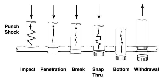
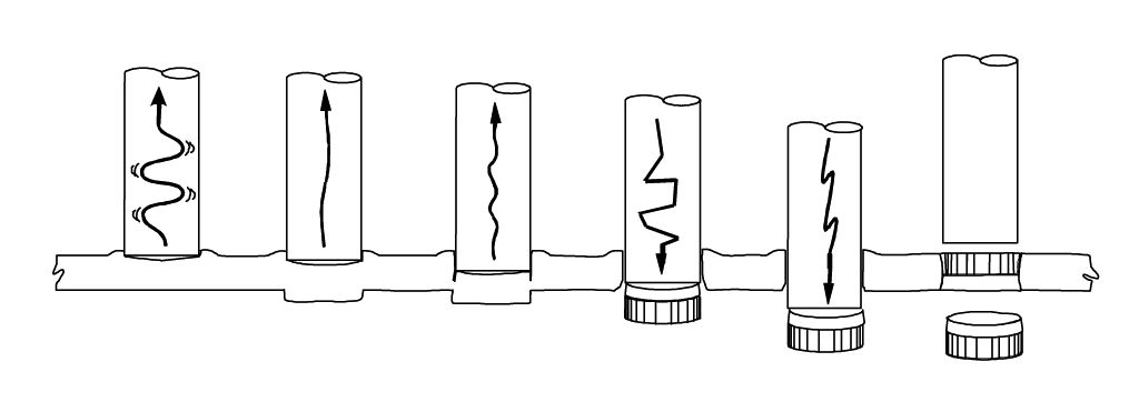
The perforating process can be broken down into six definable steps.
Each step contains elements critical to the overall process. An understanding of these steps will assist in the selection of die construction, tool steels, and punch to die clearance.
Impact
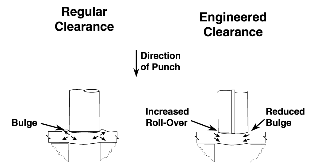
Impact is where the punch first makes contact with the part material. There is a moment where the punch comes to a stop as the backlash and flex of the ram and press are taken up.
A compressive load rapidly builds, sending a shock wave up through the punch. The part material begins to bulge around the point of the punch.
Penetration
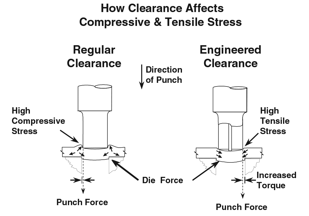
As the yield strength of the part material is exceeded by the power of the press, the point of the punch begins to penetrate the part’s surface. Both punch and matrix begin to cut from their respective sides.
The leverage set up by the die clearance allows the punch to bend the slug. The center of the slug bows away from the punch creating a vacuum pocket, which will become a factor in later steps.
Break
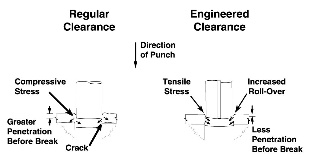
Once the part material is deformed and stretched to its tensile limits, it begins to crack between the cutting edges of the punch and matrix. This subsequently generates the break found in the finished hole and on the outside diameter of the slug.
Snap Thru
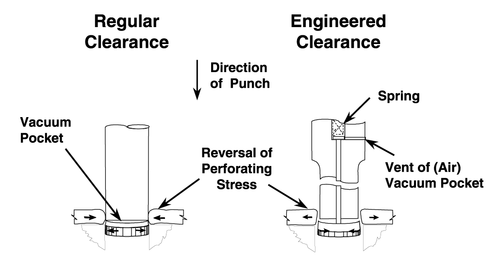
When the tensile limits of the part material are exceeded, the slug suddenly separates from the part. This sudden unloading of pressure on the punch generates a reverse shock that often leads to punch head breakage.
Snap Thru shock has a direct relationship to part material hardness. Harder and stronger part material generates the greatest shock.
Compare the direction of part material spring back once the slug has broken free. With Regular Clearance the hole in the part has closed the end of the punch. The slug has expanded and is jammed in the matrix.
The opposite reaction occurs when Jektole® Clearance is applied, minimizing potential slug jamming problems. A hole in the side of the punch vents the vacuum pocket allowing the ejector pin to push the slug away without resistance.
Bottom
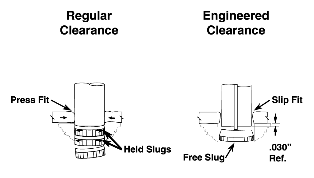
When the ram of the press reaches the bottom of its stroke, the punches should only enter the matrix approximately .020" to .030".
More entry will create excessive wear, particularly when using Regular Clearance. It can also cause slug pulling. The further a punch is entered, the more vacuum it creates at withdrawal. This vacuum will likely pull slugs.
Withdrawal
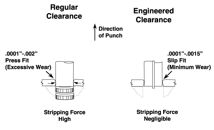
Withdrawal of the punch from the part material can generate as much as two thirds of the punch wear and be responsible for allowing slug pulling.
Because Regular Clearance can produce a hole that is as much as .002" smaller than the point of the punch, it creates a press fit condition on the point of the punch in every hit. Abrasive wear on both punch and matrix will be excessive.
Jektole® Clearance produces a hole that is larger than the point of the punch leaving a slip fit condition and eliminating as much as two thirds of the wear incurred when using Regular Clearance.
When increasing clearance, the size of the slug is reduced. This leaves it loose and free to pull up at withdrawal. The ejector pin solves that by pushing the slug free of the punch.
Jektole® Clearance can be applied as long as there is a means of slug control.
Tight Clearance
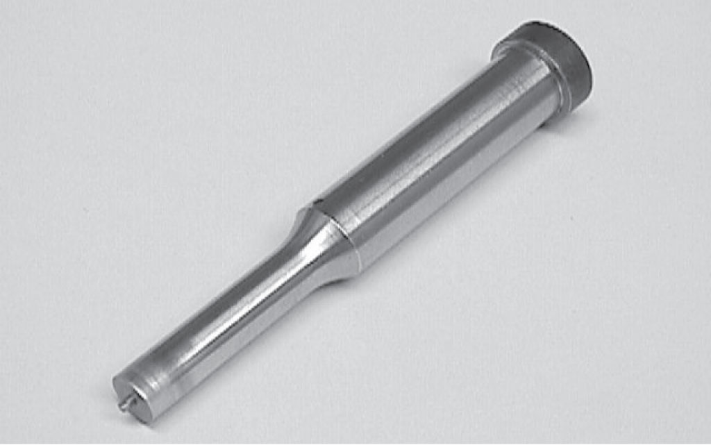
This example also illustrates the effects of tight clearance. The rings around the point indicate that the part material has sprung back on the point at snap-thru grabbing the end of the punch. This tight fit on the point has generated heat discoloring the area just behind the tip, potentially damaging its heat treat. Tool life due to heat damage will be reduced.
Punch Tip Pulling
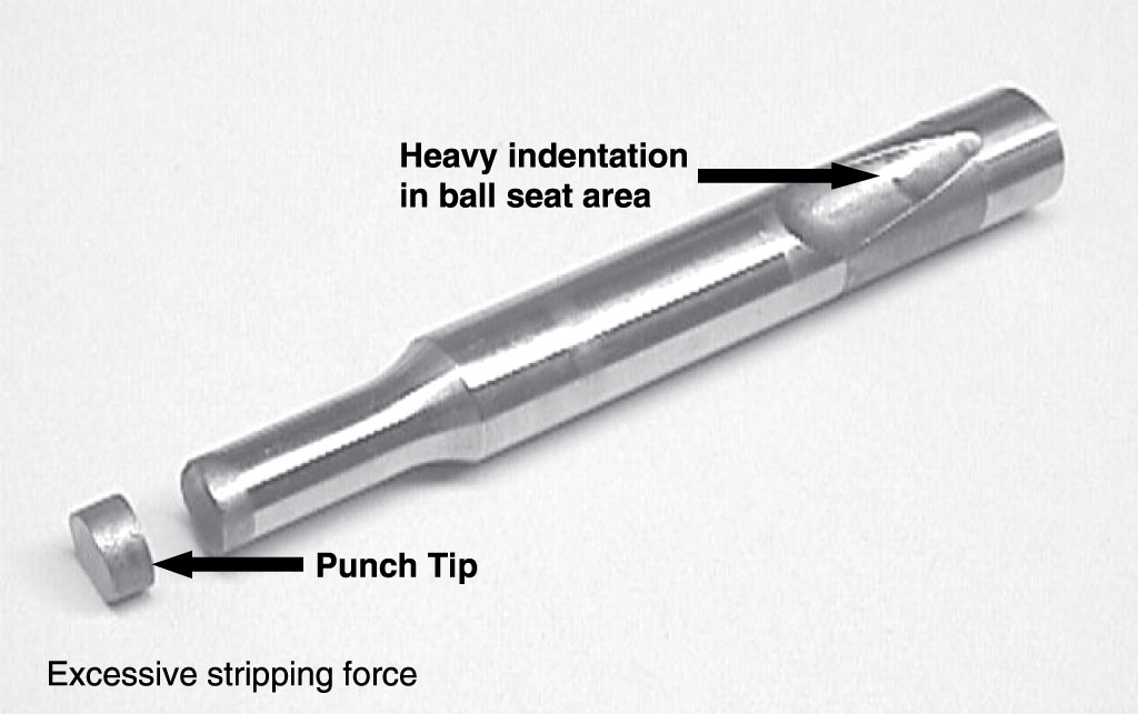
Severe tight clearance can fatigue and eventually pull the end of the punch off. Note the impression of the ball in the ball seat area indicating excessive stripping force associated with tight clearance.
Hole Characteristics
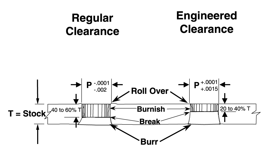
Hole characteristics vary with different clearances. Regular Clearance typically results in a high percentage of shear or burnish with minimal roll-over and break. The hole tends to be smaller than the punch point.
Jektole® Clearance achieves a low percentage of shear or burnish, with greater roll-over and break. The hole size will be larger than the point of the punch.
Hole Size Comparison
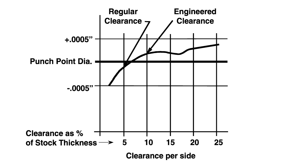
A comparison of holes perforated with Regular Clearance verses Jektole® Clearance reveals the advantage of increasing clearance between punch and matrix.
As punch to matrix clearance increases, the hole size in relation to punch point size becomes larger, reducing stripping friction and wear. The result is longer punch life.
Burr Generation
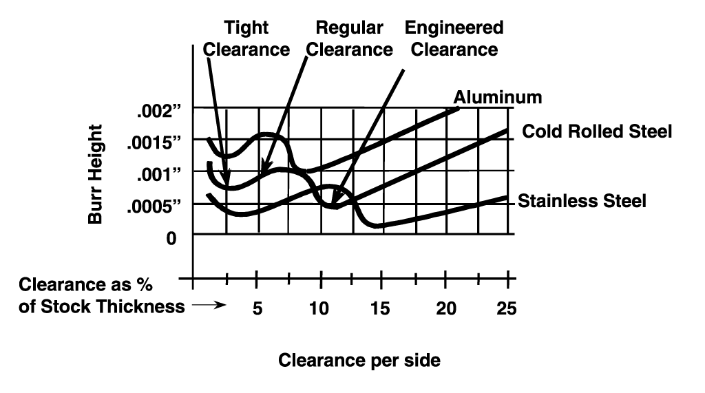
Burr height is also affected by punch to matrix clearance. Regular Clearance offers acceptable burrs in many cases. As the clearance increases slightly, the burr height increases.
Substantial increases in punch to matrix clearance will reduce the burr height below that of Regular Clearance in most applications.
Productivity
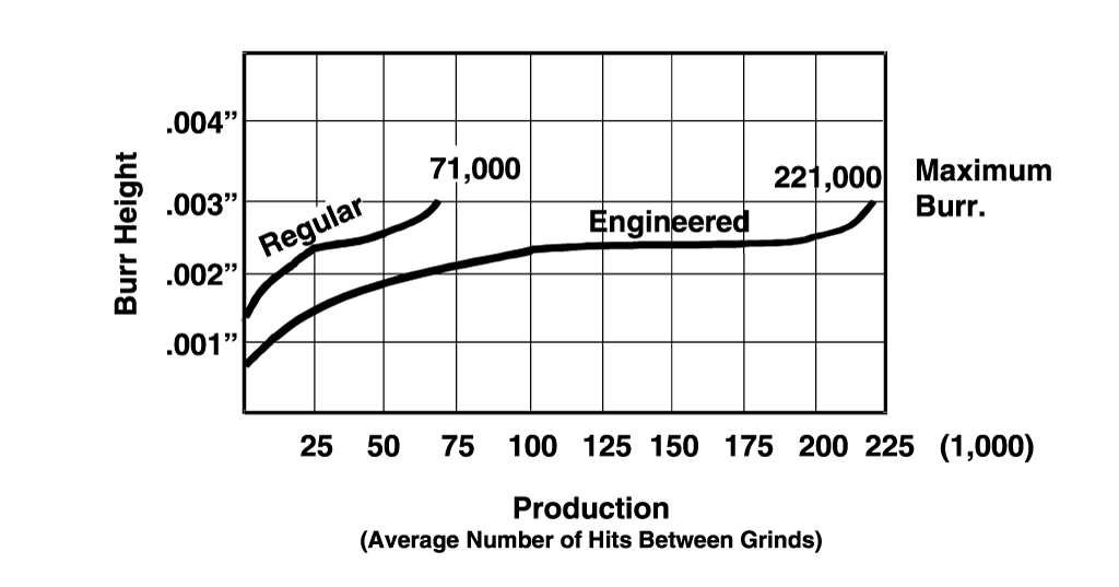
A case study based on .060" thick cold rolled steel revealed a three-fold increase in punch life.
Hole Size to Stock Thickness Association
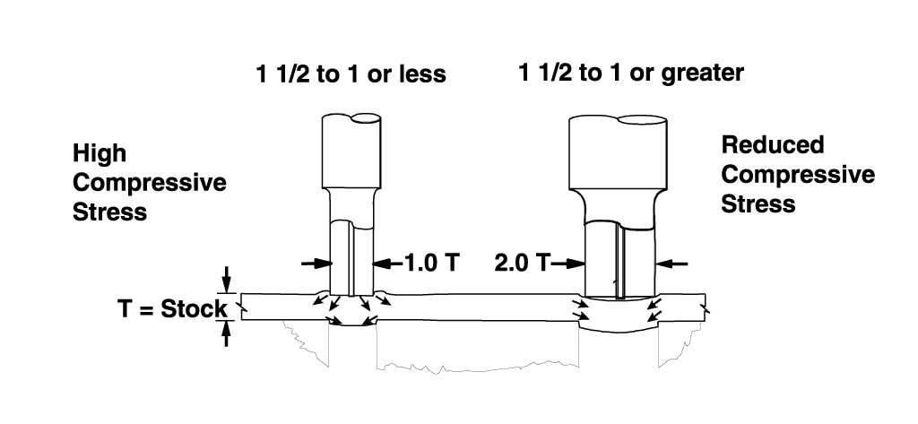
A general practice in designing and building a stamping tool is to apply a common punch to matrix clearance regardless of hole size.
There comes a point when a hole size becomes too small in relation to the part material thickness for the same clearance to be effective. The small hole results in higher punch loading, longer burnish in the hole and excessive burr.
This phenomenon begins to occur when the hole size drops below 1 1/2 times the part material thickness. At that point it becomes more difficult to bend and cleanly break the slug free.
Increased leverage to bend and break the slug can be achieved by increasing the punch to matrix clearance. 1% per side clearance should be added to the existing clearance when the hole size is 1 1/2 times part material thickness and increased as the hole size becomes smaller. A hole size that is equal to the part material thickness will need approximately 4% per side additional clearance.
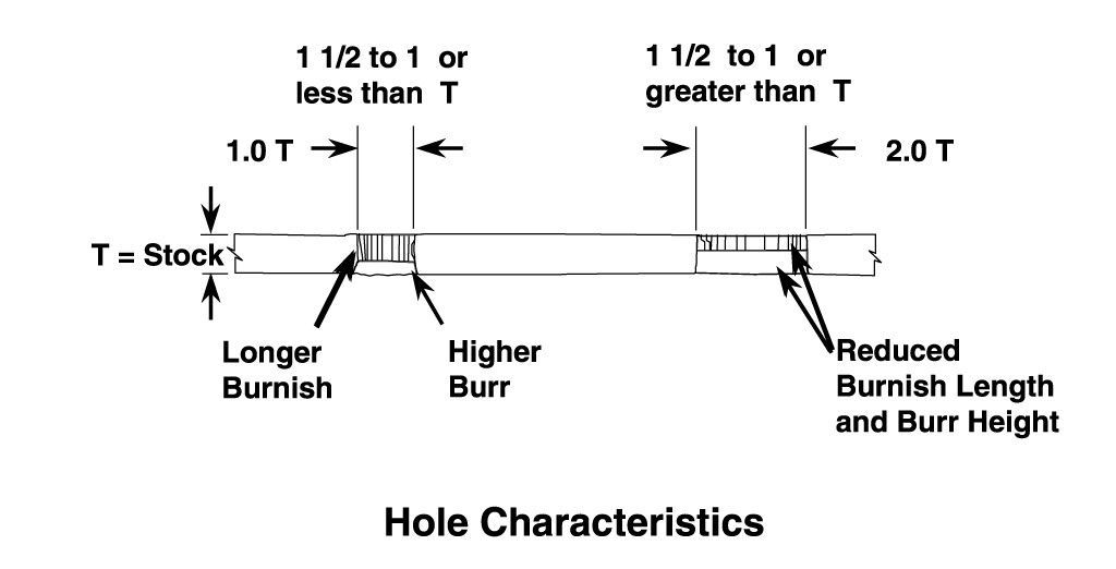
The resulting hole from a nearly one to one ratio of the punch point diameter to material thickness will have different characteristics from the larger holes.
Small diameter holes that are less than 1 1/2 times the material thickness will have a longer burnish length, larger burr and the hole diameter will tend to be smaller than the punch point diameter, all of which reduce the life of the punch and matrix.
Hole Diameter to Stock Thickness Ratio
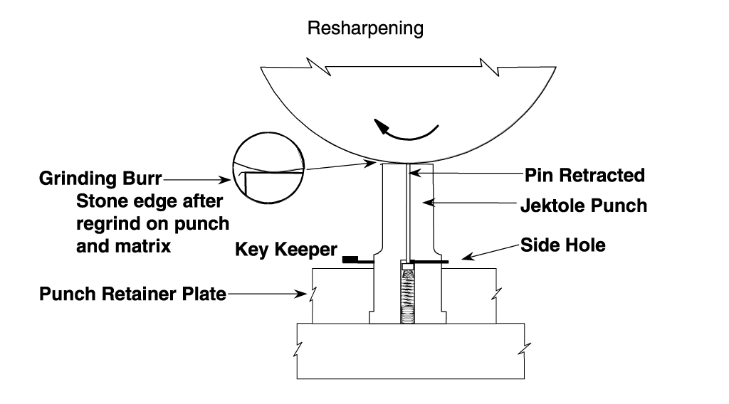
The side vent hole in Jektole® punches serve two functions. One function is to minimize the suction at withdrawal that can cause slug pulling.
The other function is to allow the use of a keeper key to lock the Jektole in the retracted position. This function makes it possible to sharpen the punch without disassembly.
Point Chipping
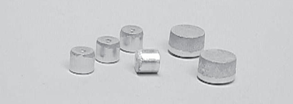
Burnish and break on the slug will be affected in much the same manner as seen in the hole. All of the slugs pictured above are the result of 6 percent per side punch to matrix clearance.
The larger diameter slugs have approximately 25% burnish. This is typical for most applications where the hole diameter is more than 1 1/2 times the material thickness.
The slug becomes more difficult to bend and break out when the hole size is less than 1 1/2 times the material thickness. Note that the smaller diameter slugs in the illustration have considerably more burnish and less break. Burr height is also heightened under these circumstances. Their diameter is equal to the material thickness.
Leverage needs to be increased in order to bend and break out the smaller slugs. This is achieved by increasing the punch to matrix clearance. Increasing the punch to matrix clearance reduces the amount of pressure required to perforate the hole or blank out a slug.
Clearance Testing
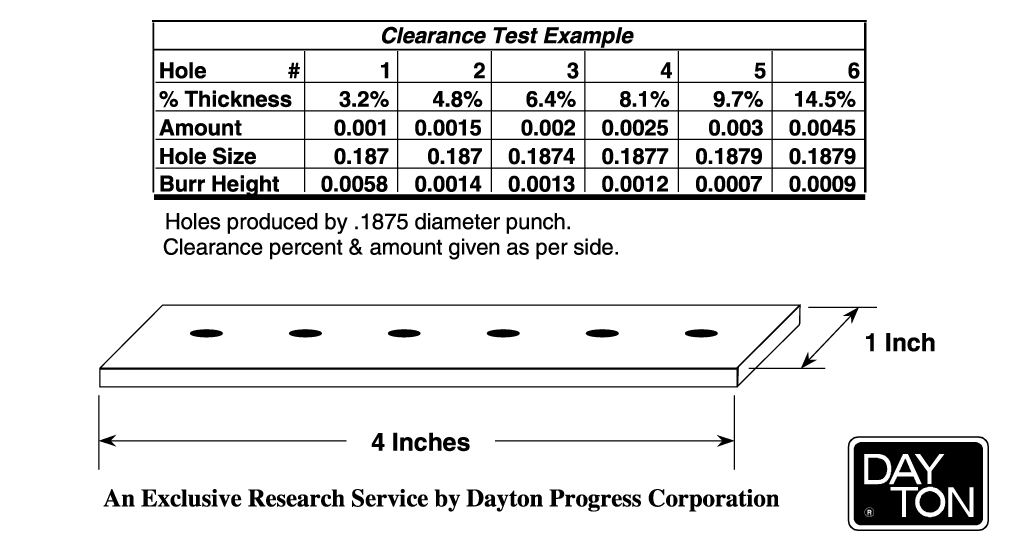
Learn more about our Jektole Clearance Testing Service.




 Printable PDF